Brake Test On 3 Phase Induction Motor Circuit Diagram Wiring
[diagram] connecting diagrams for induction motors Induction connection cage squirrel wiring starter troubleshoot stator resistor polyphase voltage reduced reactor Clutch brake connection diagram with motor and rectifier module
Methods of Starting 3-Phase Induction Motors
Brake test on dc shunt motor lab manual pdf Brake test on three phase slip ring type induction motor How to troubleshoot 3 phase induction motor : step by step guide
3 phase induction motor ( 195 v
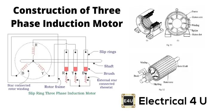
Clutch brake motor connection diagram rectifier moduleWhat is 3 phase induction motor? diagram, working & types Motor phase induction three construction slip ring diagram rotor cage squirrel motors circuit wound engineering main parts resistance connected electricalSpecial tests of 3 phase induction motor.
Three phase induction motor electric fan, electric powerMethods of starting 3-phase induction motors Kabellos freundin cafe induction motor circuit diagram nackt komm mit randEquivalent circuit of a three phase induction motor – valuable tech notes.

Three phase induction motor
Induction electricalworkbook rotorBrake test on the 3-phase induction motor Three phase induction motor1 phase induction motor circuit diagram.
Three phase induction motor circuit diagram3 phase motor circuit Three phase induction motor: types, working, and applicationsWhy three phase induction motor self-starting but synchronous motor not.

Motor connection diagram three phase
How to test 3 phase motorSpecial tests of 3 phase induction motor Clutch brake motor connection diagram rectifier module || 3 phase motorBrake moteur frein wiring freno câblage collegamento connection anschluss schneider.
Equivalent circuit diagram of induction motor[diagram] wiring diagram of 3 phase induction motor Induction principle componentsConnection motor phases and holding brake (cn10 and cn11).
Brake test on a three phase slip ring induction motor
Induction motor phase three construction working types applications electrical circuitThree phase motor chart Induction wiringInduction phase circuit tests transformer.
3phase motor winding diagramConstruction of three phase induction motor Induction tests phase special3 phase induction motor circuit.

Wiring diagram of direct on line starting three phase induction motor
How to wire 3-phase induction motor? .
.


How to Wire 3-phase Induction Motor? | ATO.com

Three Phase Motor Chart | My XXX Hot Girl

Connection Motor Phases and Holding Brake (CN10 and CN11)

How to test 3 phase motor | induction motor testing by using multimeter

Why Three Phase Induction Motor Self-Starting but Synchronous Motor not

3 Phase Induction Motor ( 195 V - 3,7 A - 290 Hz ) How to operate

Clutch Brake Motor Connection Diagram Rectifier Module || 3 Phase Motor